Table of Contents
inductor definition-
When electric current is passed through a coil, the device that opposes the change in current is called an inductor and the opposition or obstruction of sudden change in current by the inductive effect of this inductor is called inductance.
what is inductor?
The inductor stores magnetic flux, with larger valued inductors capable of storing
more flux. Inductance has units of henries (H), and is named for the American
physicist Joseph Henry. The differential and integral forms of the inductor’s v-i
relation are

The power consumed/produced by an inductor depends on the product of the
inductor current and its derivative

and its total energy expenditure up to time t is given by

inductor unit-
The unit of inductance is Henry and it is represented by (H).
Another unit of inductance is weber per ampere.
The components which show the property of inductance are called inductors.
The inductor has the property of electrical inertia.
inductor symbol
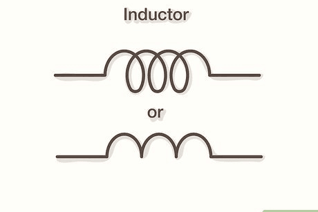
The symbolic sign of the motivator is shown as follows. common symbol (L)
inductor formula-
Voltage across an inductor–
An inductor is made by coiling a conductor, that is, when the current in the coil changes, an induced electromotive force is produced as a result of the change in flux relative to it.

the rate of change of flux.

where N = number of turns in the coil dt
Due to this induced electromotive force (E), in addition to the main current, an additional induced current also flows. Which, according to Lenz’s law, always opposes the change in the main current.
The negative (-) sign of the induced e.m.f. represents Lange’s law.
Types of Inductor-
Inductors are of three types based on the core-
- Air core inductors
- Iron core inductors
- Ferrite core inductors
Air core inductor
No core of any kind is used in this type of inductor.
The advantage of air cores is that they do not undergo saturation. Hence they are used in high frequency applications.
Ferrite core inductor
In this type of inductor, iron and copper metals are mixed as core.
The resistance of ferrite core is very high, hence this type of core is used in transformer to obtain minimum reluctance path.
Inductors of this type of core are used for variable values. Such as they are used in transmitters and receivers.
Iron core inductors-
In this type of inductor, the core is made of soft iron because soft iron can easily acquire electromagnetic properties.
Soft iron has the highest inductance value.
Iron core is used in machines.
Self Inductance-
If the coil opposes the current flowing through it, then the property of the electromotive force generated due to change in current is called self induction.
Example: The electromotive force generated in the primary of a transformer is the result of self-induction.
Self-induction is symbolically represented by “L”.
That is, the induced current opposes both increasing and decreasing the main current value in the coil.
Coefficient of Self Inductance-
We know that if a coil is made of (N) number of turns and current is passed through this coil, then due to current, flux leakage (Flux-Leakage number will be (ND). This number will be proportional to the current flowing in the coil.
L=_μομ,ΑΝ²/l where
- L = value of inductor
- N = turn number
- $ = value of flux, in webers
- 1 = electric current, in amperes
- S = reluctance in the magnetic circuit
- l = length of the magnetic circuit
- A = cross sectional area
- 50 = air permeability
- µo = 4 × 10⁻⁷ henry/meter
- µ, = relative permittivity
- μ2 = unit less quantity
The unit of self inductance is henry.
Dimension of self-induction coefficient (L) [ML2T-2A-2]
1 Henry- If an induced electromotive force of 1 volt is generated in a coil when the current changes at the rate of 1 Amp / Sec, then the self-induction coefficient of the coil is 1 Henry
coefficient of coupling
The coefficient of coupling (k) between two coils is defined as the fraction of magnetic flux
produced by the current in one coil that links the other.
When the entire flux of one coil links the other, coefficient of coupling is 1 (i.e., 100%). If only
half the flux set up in one coil links the other, then coefficient of coupling is 0·5 (or 50%). If two coils have self-inductances L1 and L2, then mutual inductance M between them is given by
Mutual Inductance-
When two coils are situated closest to each other, then due to change in current in one coil, magnetic flux is generated in the other coil due to which voltage is generated in the second coil, that principle is called mutual induction
Let us assume two coils whose self-induction value is L₁ and L₂ respectively, which are placed near each other.
So, if number of cycles in first coil = N₁, then number of cycles in second coil = N₂
In the figure, self-induction is shown by 11 and mutual induction is shown by $12.
If current is passed through the first coil, then the value of flux is: Total flux = Primary leakage flux + Secondary mutual flux
Φ1 = Φ11 + Φ12 Voltage generated in the first coil
Coupling Factor-
The coupling coefficient (K) of two coils is the measure of coupling of the coils. Suppose two coils have self inductance L₁ and L₂ and their mutual inductance is M, then-

K = Coupling coefficient of two coils
“K” shows how much percentage the flux of a coil is linked to the other coil.
- The value of K for a coil is always less than one. (K≤1)
- In an ideal transformer the value of coupling factor K is unity (1)
- In an isolated magnetic circuit the coupling coefficient is zero.
Inductors in Series
Consider two coils connected in series as shown in
Let
L1 = inductance of first coil
L2 = inductance of second coil
M = mutual inductance between the two coil
Inductors in series formula:
(i) Series-aiding.
This is the case when the coils are so arranged that their fluxes aid each other. in the same direction as shown in(i). Suppose the current is changing at the rate di/dt. The total induced e.m.f. in the circuit will be equal to the sum of e.m.f. induced in L1 and L2 plus the mutually induced e.m.f.s, equal


It is generally not possible to tell from the picture whether the phalanges of two Kundalis are compatible or in opposition. Dot Notation removes this misconception. The hole of the Kundali through which the thread enters is shown by putting a dot behind it. If after taking out the thread from the bindidar hole of Kundali L1, the thread enters the bindidar hole of Kundali L2, then it means that the phalanges of both the Kundalis are compatible or in opposition.
Series-opposing.
anti-series connection means two coil fluxes oppose each other. The flow of current is changing with the rate of di/dt. The total induced e.m.f. in the circuit will be equal to the reduction of induced emf. in L1 and L2 by mutually induced emf.

Inductors in Parallel with no Mutual Inductance

If the coils are placed so that the fluxes produced by them are at right angles to each other, then the mutual flux will be zero and hence M = 0
Inductors in Parallel with Mutual Inductance
Two coils A and B with inductances L1 and L2 are connected in parallel as shown in Fig. . Let the mutual inductance between the two coils be M. The supply current i is split into two branch currents i1 and i2.


example-1
When two coils are connected in series, their effective inductance is found to be 10 H. When the connections of one coil are reversed, the effective inductance is 6 H. If the coupling coefficient is 0.6, calculate the self-inductance and mutual inductance of each coil.

example-2
The total inductance of two coils, A and B, when connected in series, is 0.5 H or
0.2H, depending upon the relative direction of the currents in the coils. Coil A, when isolated from coil B, has a self-inductance of 0.2 H. Calculate (i) the mutual inductance between the two coils, (ii) the self-inductance of coil B, (iii) the coupling factor between the coils, and (iv) the two possible values of the induced e.m.f. in coil A when the current is decreasing at 1000 A/s in the series circuit.


example- 3,4

Energy Stored Inductors-
Inductor stores energy in the form of magnetic field.

where –
- W= Stored energy (W)
- L = value of inductor (Henry)
- I = value of current (Ampere)
Energy Stored in a Magnetic Field
In order to establish a magnetic field around a coil, energy is *required, though no energy is
needed to **maintain it. This energy is stored in the magnetic field and is not used up. When the current is decreased, the flux surrounding the coil is decreased, causing the stored energy to be returned to the circuit. Consider an inductor connected to a d.c. (i). The inductor is equivalent to inductance L in series with a small resistance R (ii). The energy supplied to the circuit is spent in two ways :
*
When the coil is connected to supply, current increases from zero gradually and reaches the final value I (= V/R) after some time. During this change of current, an e.m.f. is induced in L due to the change in flux linkages. This induced e.m.f. opposes the rise of current. Electrical energy must be supplied to meet this opposition. This supplied energy is stored in the magnetic field.- **
To impart a kinetic energy ofmv2 to a body, energy is required but no energy is required to maintain it
(i) A portion of the supplied energy is consumed to meet I2R losses and cannot be recovered.
(ii) The remaining portion is used to create flux around the coil (or inductor) and is stored in the magnetic field. When the field collapses, the stored energy is returned to the circuit.

Mathematical Expression

The energy stored in an inductor depends on its inductance and the current passing through it. For a given inductor, the amount of energy stored is determined by the maximum current that flows through it. Note that the energy stored will be in joules if the inductance (L) and current (I) are measured in Henries and amperes, respectively.
note-
If the current in an inductor varies, the stored energy rises and falls in step with the current. Thus, whenever the current increases, the coil absorbs energy, and whenever the current falls, energy is returned to the circuit.
Alternate method of Energy Stored Inductor
In order to determine the amount of energy an inductor stores, we need to determine inductor’s current and voltage during the time it is storing energy. Since the inductor stores energy only during the time the current is increasing, we must determine the average current during the time the current is rising. This can be done by referring to Fig. 9.27 which shows the current in an inductor increasing at a constant rate until it reaches the maximum value Im. Since the current rises linearly from 0 to Im, the average value of current is


Magnetic Energy Stored Per Unit Volume
Consider a coil of N turns wound over a magnetic circuit of length l metres and uniform cross
sectional area of ‘a’ m2.


Note that magnetic energy stored will be in joules if the flux density B is in Wb/m2.
Lifting Power of a Magnet
When two opposite polarity magnetic poles are separated by a short distance in air, there is
a force of attraction tending to pull the two poles together. The magnitude of this force can be
calculated in terms of flux density in the air gap and cross-sectional area of the pole.
Consider two poles, north and south, each of area ‘a’ square metres, separated by a short distance in air as shown in Fig. 9.29. Let P Newtons be the force of attraction between the two poles. If one of the poles, say the S-pole, is pulled apart through a small distance dx, then work will have to be done against the force of attraction.

Note that P is the force of attraction at each pole. In a practical magnet, there are two poles
(See Fig. 9.30) so that total force of attraction is 2P. Electromagnets are widely used for commercial lifting jobs such as loading scrap iron into a truck or raising an armature to a higher position.
Closing and Breaking an Inductive Circuit
Consider an inductive circuit shown in Fig. 9.34. When
switch S is closed, the current increases gradually and takes
some time to reach the final value. The reason the current does
not build up *instantly to its final value is that as the current
increases, the self-induced e.m.f. in L opposes the change in
current (Lenz’s Law). Suppose at any instant, the current is i
and is increasing at the rate of di/dt.
Then,
V = vR + vL

The current is zero at the instant the switch is closed because it must start from zero.
Now, self-induced e.m.f., vL = di/dt
If current change (i.e.di) is instant, it means di/dt = 0. This means that L is infinite which is impossible. So it is not possible for current in inductance to change from one value to the other in zero time.

As the current increases, vR (= iR) increases and vL decreases since V is constant. The decrease in vL (= L di/dt) means that di/dt decreases because L is constant. The result is that after some time, di/dt becomes zero and so does the self-induced e.m.f. vL (= L di/dt). At this stage, the current state attains the final fixed value I given by ;

Thus, when a d.c. circuit containing inductance is switched on, the current takes some time
to reach the final value I (= V/R). Note that the role of inductance is to delay the change; it cannot prevent the current from attaining the final value. Similarly, when an inductive circuit is opened, the current does not jump to zero, but falls gradually. In either case, the delay in change depends upon the values of L and R as explained in the next article.
Rise of Current in an Inductive Circuit
Consider an inductive circuit shown in Fig. 9.34. When switch S is closed, the current rises
from zero to the final value I (= V/R) in a small time t. Suppose at any instant, the current is i and is increasing at the rate of di/dt. Then.

*Multiplying both sides by –R, we get,

Integrating both sides, we get,

where K is a constant whose value can be determined from the initial conditions. At t = 0, i = 0. Putting these values in exp. (i), we have, loge V = K.
Equation (i) becomes :

But V/R = I, the final value of current attained by the circuit.
i = I(1 – e–Rt/L)

Eq. (ii) shows that rise of current follows an exponential law (See Fig. 9.35). As t increases, the term e–Rt/L gets smaller and current i in the circuit gets larger. Theoretically, the current will reach its final value I (= V/R) in an infinite time. However, practically it reaches this value in a short time.
Note. V = iR + L di/dt
At the instant the switch is closed, i = 0
The initial rate of rise of current in an inductive circuit helps us in defining the time constant of the circuit.
Decay of Current in an Inductive Circuit
Consider an inductive circuit shown in Fig. 9.37. When switch S is thrown to position 2, the
current in the circuit starts rising and attains the final value I (= V/R) after some time as explained above. If now switch is thrown to position 1, it is found that current in the R – L circuit does not cease immediately but gradually reduces to zero. Suppose at any instant, the current is i and is decreasing at the rate of di/dt. Then

where K is a constant whose value can be determined from the initial conditions. When t = 0, then
i = I (= V/R).

Combination of Inductor-
series order combination
parallel serial combination
From an experimental point of view, the numerical property of an inductor is similar to that of resistance
series order combination
Hence Leg = L₁+ L₂ + L₂—Ln
Note- If (n) inductors of the same value are connected in series then the value of equivalent inductance will be nL.
Example- If in a circuit three inductors whose values are 4H, 5H and 10H respectively are connected in series, then find the value of equivalent inductor.
Solution- We know that inductors in series
Leg = L + L₂ + L + +L
अत: L = 4+5+10 = 19 H
Inductive parallel combination
inductors of the same value are connected in parallel then the value of equivalent inductance will be -L/n.
Dot Rule-
It is represented by (.).
According to Dot rule, if there is a Dot (.) at the end from which the current is entering then it will become the (N pole) and the side where there is no Dot (.) will become the (S pole).
Situation 1-
If two inductors or coils are connected in series with points of the same polarity, then positive mutual induction will be obtained in both.
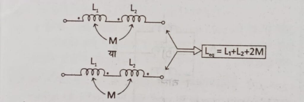
Situation 2
If two inductors or coils are connected in series with points of opposite polarity then there will be negative inductance between the inductors.
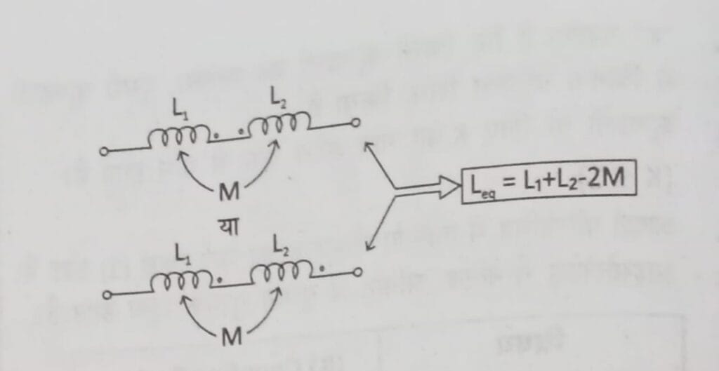
Situation 3-
If inductors or coils are connected in parallel with the same polarity then there is mutual inductance (adding nature) between the two inductors.
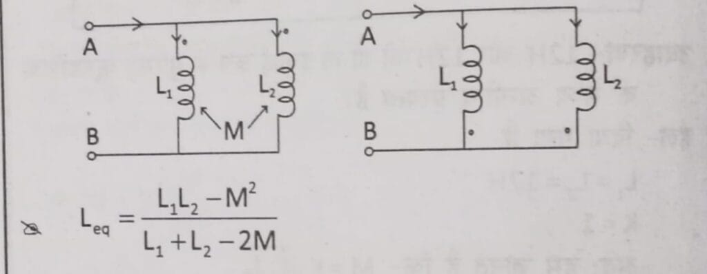
Situation 4-
If two phases or coils are connected in parallel with points of opposite polarity then the mutual inductance between the inductors is of sub-tractive nature.
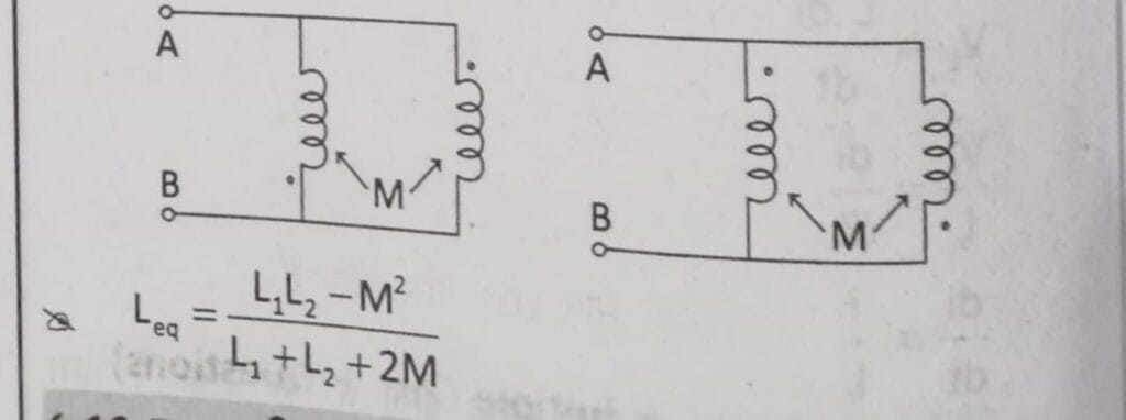
Time Constant-
The time constant is defined for either charging or dischanging.
For an inductive circuit, the time constant during which the inductance charge takes place is called the charge time.
In an inductive circuit, the value of time constant where the inductor (36.8% left) is called discharging time.
Time Constant (τ) = L/ R second
That is, by increasing the resistance in the circuit the time constant decreases.
An inductor started from an ideal current source gets charged instantly.
In a pure inductor the power consumption is always zero.
inductors uses-
Energy Storage: Inductors store energy in a magnetic field when a current flows through them, and they can release this energy when the current changes.
Filtering:Inductors, often used with capacitors, form filters that block or pass specific frequencies, making them essential in audio equipment, power supplies, and communication systems.
Tuning Circuits:Inductors are used in conjunction with capacitors in tuning circuits to select specific frequencies, such as in radios and televisions.
Transformers:Inductors are the core components of transformers, which transfer energy between circuits.
Sensors: Inductors can be used as sensors in various applications, such as proximity sensors and metal detectors.
Power Supplies and DC-DC Conversion: Inductors store energy and regulate current flow in power supplies, helping to stabilize output voltage and reduce noise.
Other Applications:Inductors are also used in lighting systems, medical equipment, and induction motors.
exam useful important facts
The property of a coil due to which counter EMF is generated due to change in current in it is called self-induction.
The property of a substance which opposes the occurrence of magnetic flux is called reluctance.
According to Lenz’s law, induced EMF and current oppose each other.
The flux will correspond to the current as compared to the electric field and the magnetic field.
When an electromagnetic circuit is switched off, sparking occurs at the switch contacts due to high inductance.
Sparking between the contacts of a switch in a circuit can be eliminated by connecting a capacitor across the switch terminals.
The time constant of the circuit is the time taken for the current to become 63.2% of its final value.
The unit of inductance is Henry and it is represented by (H).
Another unit of inductance is weber per ampere.
The unit of mutual inductance is Henry.
The inductor stores energy in a magnetic field.
The power factor of a pure inductor is always zero lagging.
- In an inductive circuit, the current lags behind the voltage at right angles.
-Air core inductors are used in radio frequency applications.
- An inductors connected to a DC voltage source will behave like a short circuit in steady state.
- In a pure inductive AC circuit, the current lags the voltage by 90°.
The value of 1 Tesla is 104 Gauss.
read more-
FAQ
Why star delta starter is preferred with induction motor?
Star delta starter is preferred with
induction motor due to following reasons:
• Starting current is reduced 3-4 times of
the direct current due to which voltage
drops and hence it causes less losses.
• Star delta starter circuit comes in circuit
first during starting of motor, which
reduces voltage 3 times, that is why
current also reduces up to 3 times and
hence less motor burning is caused.
• In addition, starting torque is increased
and it prevents the damage of motor
windingWhat are the advantages of star-delta starter with induction motor?
:(1). The main advantage of using the star delta starter is reduction of current during the
starting of the motor. Starting current is reduced to 3-4 times Of current of Direct online
starting.(2). Hence the starting current is reduced , the voltage drops during the starting of motor in systems are reduced.. Why series motor cannot be started on no-load?
Series motor cannot be started without load because of high starting torque. Series
motor are used in Trains, Crane etc.
