Table of Contents
What is a DC Generator?
A DC Generator is a machine that makes electricity. But not just any electricity — it makes DC electricity, which means Direct Current.
Let’s make it super easy to understand.
Imagine you have a toy fan that runs on batteries. The batteries give it power in one single direction — that’s DC power. A DC Generator also gives power like that, but instead of using batteries, it makes its own electricity by spinning a coil inside a magnetic field.
⚙️ How does it work?
Think of a wheel spinning very fast. Inside the generator, there’s a coil (a wire loop) that spins between magnets.
When the coil spins, it cuts through the magnetic lines — this movement creates electricity.
That electricity flows in one steady direction — this is called Direct Current (DC).

Types of DC generator:
Types of a DC generator based on way in which the field are excited generator are classified
DC machines
- Permanent magnet
- Separately excited
- self excited
Separately excited
- voltage excited
- current excited
self excited
- Series
- Sunt
- Compound
Compound
- Long shunt
- Short shunt
- cumulatively compounded
- Differentially compounded
types of dc generator with diagram

types of dc generator with diagram
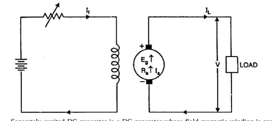
Separately Excited DC Generator
A separately excited DC generator is a special kind of generator where the field winding and the armature winding are not connected to each other. They work separately, just like two people doing their own jobs to keep everything running smoothly.
How does it work?
The generator needs a magnetic field to create electricity. This magnetic field can be created in two ways:
- By using a separate power supply to give electricity to the field winding.
- By using strong permanent magnets instead of coils and windings.
We usually use the first method—connecting a separate DC voltage source to the field winding. This is like giving a battery to the field part so it can build a strong magnetic field.

What is the field winding?
The field winding is made up of thin copper wire wrapped in many turns. It’s designed to have high resistance, which means it doesn’t let current flow too easily. This helps it control the magnetic field properly.
Now, what happens in the generator?
Let’s say:
Vis the voltage you get at the output (the terminal voltage),Eis the actual voltage generated inside the armature (called emf),Iais the current in the armature, andRais the resistance of the armature winding.
Using a simple rule from electricity (Kirchhoff’s Law), we can say:
E = V + Ia × Ra
Or simply:
V = E − Ia × Ra
This tells us that the voltage at the output is a little less than what is actually generated inside. This is because some voltage gets lost inside the armature wires due to resistance.
What about the brushes?
DC generators use carbon brushes to transfer electricity. These brushes also cause a tiny voltage drop, usually around 2 volts. It’s small, but it matters. We include this drop in our total calculation for better accuracy.
Think of it like water flowing through a pipe: a little bit always sticks to the sides!
Understanding Generator Performance
To know how well a DC generator is working, we check a few important curves:
- Open Circuit Characteristic (OCC): This shows how the generator builds voltage when there’s no load connected.
- Internal Characteristic: This shows what happens inside the generator when current flows.
Magnetization Characteristic of a DC Generator
(Also called No-Load Characteristic)
Let’s understand this step by step in a very easy way.
When a DC generator runs without any load connected to it, it still produces voltage. The way this voltage changes with the field current (the current given to the field winding) is called the magnetization characteristic.
Imagine a graph where we are increasing the field current slowly, and we watch how the voltage across the generator’s terminals increases. We draw that on paper. That curve is called the magnetization curve or no-load characteristic.
How It Works:
- No Load = No Armature Current
When the generator is not connected to any load, the armature current is zero. That means there is no voltage drop inside the machine due to resistance. So the voltage at the terminals is the same as the voltage actually generated inside. - Residual Magnetism – The Magic That Starts It All
Even when no current flows in the field winding, a tiny magnetic field is already there inside the generator. This is called residual magnetism. It helps the generator produce a small voltage even at the very beginning. This is what helps the machine “kick-start” the voltage generation. ➤ If there is no residual magnetism, then we have to give power to the field winding first to start building up the magnetic field. - What Happens As We Increase Field Current?
- At first, the generator’s magnetic parts (called poles) are not full. So the magnetic field (called flux) increases nicely and linearly.
- But after some time, the poles start to get full — we call this magnetic saturation. Now, even if we increase field current more, the flux does not increase much.
- So, we need to increase the field current a lot more to get a small increase in voltage.
External Characteristics of a DC Generator
Let’s understand it in a very easy way.
When a DC generator runs, it produces electricity. Now, imagine you’re switching on different devices — a fan, a light, a machine — this is called putting load on the generator. The more things you switch on, the more current flows.
But how does this affect the generator’s voltage?
That’s where external characteristics come in.

🔌 What Are External Characteristics?
These characteristics show how the output voltage (the voltage at the terminals of the generator) changes as you increase the load current (how much current the generator is giving).
There’s a simple rule here:
👉 When the load is zero (nothing is connected), the current is zero too. So, the voltage you get at the terminals is the same as the voltage generated inside. This is called the no-load voltage.
But…
👉 When you start adding load, the current increases, and then the terminal voltage starts dropping a little. Why? Because of two main reasons:
⚡ Why Does Voltage Drop?
- Resistance Inside the Generator
The wires and brushes inside the generator have some resistance. When current flows through them, a part of the voltage gets used up there.
Think of it like water flowing through a pipe — if the pipe is long and rough inside, some water pressure is lost before it comes out. - Armature Reaction
When more current flows, it creates a magnetic effect that slightly weakens the generator’s main magnetic field. This is called armature reaction. Because of this, the generator can’t push out as much voltage.
📉 The Curve
If you draw a graph of how terminal voltage falls as the current increases, you get a downward curve. This is called the external characteristic curve.
Usually, the voltage drops about 5% to 10% from no-load to full load. It’s a smooth and slow drop — not sudden.
Self – excited DC generator:
A DC generator whose field magnet winding is supplied current from the output of the
generator itself is called a self-excited generator.
In a self-excited DC generator, the machine uses its own electricity to power its magnetic field. That means, it doesn’t need any outside battery or power source to excite its field winding.
Now, there are three main types of self-excited DC generators:
- DC Series Generator – Here, the field winding is connected in series with the armature.
- DC Shunt Generator (or Parallel Generator) – In this type, the field winding is connected in parallel with the armature.
- DC Compound Generator – This one has two field windings:
- One is in series,
- The other is in parallel with the armature.
This makes it a mix of both series and parallel types.
In all these generators, the field winding gets its energy from the electricity made by the armature. There is no extra power source connected to the field.
But Here’s the Problem at the Start
When the generator is not rotating, its armature is not producing any electricity. So, the field winding has nothing to excite it, and the generator cannot start building up electricity on its own. It needs a little help in the beginning.
To solve this, a few simple conditions must be met:
✅ Conditions for Self-Excitation
- There must be a little leftover magnetism (called residual magnetism) in the iron parts of the machine. This small magnetism is always there from earlier use.
- The field winding should be connected correctly, so that it helps the residual magnetism — not cancel it.
- The resistance of the field winding should be low — lower than a certain limit (this is called critical resistance).
- The generator must rotate fast enough — more than a certain minimum speed (called critical speed).
- The field circuit must be complete — meaning the switch should be closed and all wires connected properly.
There are three types of self-excited generator depending upon the manner in which the field
windings is connected to the armature winding namely.
i) Series generator,
ii) Shunt generator,
iii) Compound generator.
Series Generator
In a series generator, the field winding is connected in the same line as the armature and the load. This means everything is connected in one loop, just like one long chain.
For the generator to start working on its own (called self-excitation), this full loop must be closed. If there’s any break in the circuit, it won’t work.
Now, the same current that flows through the load also flows through the field winding. So, this winding is made of thick wire and has fewer turns — strong and short, just like a powerful spring.
Series generators are not used very often. But sometimes, we use them as voltage boosters — like a little push to help lift voltage when needed.
If we look at the diagram (Fig. 1.36), we can see how it’s all connected.
But there’s something to be careful about.
If the current becomes too high, the magnetic parts (called poles) can get saturated — like a sponge that can’t hold any more water. When this happens, the voltage drops down and can even become zero.
You can also see this clearly if you look at the generator’s external characteristics — a kind of graph that shows how voltage changes with load.
To understand the behavior of the circuit, we use Kirchhoff’s Voltage Law (KVL) in the two loops shown in the figure. It helps us figure out how voltage is shared across the different parts of the circuit.
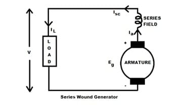
Armature current Ia = Ise = IL
Terminal voltage V=Eg-I(Ra+Rse)
Power developed in armature=EgIa
Power delivered to the load=VIa or VIL
DC Shunt Generator
A DC shunt generator is a special type of machine that makes direct current (DC) electricity. It is called a “shunt” generator because its field winding (which makes the magnetic field) is connected in parallel with the armature (the main part that produces electricity).
🌟 Why It’s Useful
- It doesn’t need outside power to start working.
- It gives a steady voltage — which means the output doesn’t change much, even when the load changes.
- That’s why it’s often used where stable electricity is needed.
How It Works (Step-by-Step)
Let’s understand how this generator starts making electricity, even without any external help.
- Starting the Generator
A machine called a prime mover (like a motor or engine) spins the armature of the generator. This is the starting point. - Tiny Magnetic Power Is Already There
Even when the generator is not running, there is a little bit of leftover magnetism (we call it “residual flux”) in the main magnetic poles. - Small Spark of Electricity Begins
As the armature starts spinning, this small magnetic force creates a tiny voltage (emf) in the winding (coils) of the armature. - Field Winding Joins the Game
Because the field winding is connected in parallel (a loop), this tiny voltage makes some current flow through the field winding. - Magnet Becomes Stronger
That small current makes the magnetic field stronger, which then increases the voltage even more. - More Current = More Voltage
As the voltage increases, more current flows through the field winding. This keeps on happening — like a snowball rolling and growing. - Voltage Builds Up Fully
Finally, it reaches a point where everything balances — the voltage and current stop increasing. This is called the equilibrium point.
🔁 What Affects This Process?
- How strong the leftover magnetism is
- The resistance of the field winding
- The speed of the rotating armature
If any of these things are not just right, the generator might not build up enough voltage. So it’s important to keep the generator in good condition.
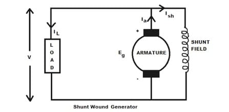
Shunt field current Ish=V/Rsh
Arm current, Ia=IL+Ish
Terminal voltage V=Eg-IaRa
Power developed in armature=EgIa
Power delivered to load=VIL
DC Compound Generator
In a compound wound generator, there are two sets of field windings on each pole, one is in
series and other is in parallel with the armature. There are two types of compound wound generator.
A DC compound generator is a special type of DC generator that uses two coils (windings) to control its magnetic field. Think of it like a team where two players work together to make the machine work better!
🧲 Two Field Windings – Working Together
This generator has two types of field windings:
- Series winding – connected in line with the armature (main power-producing part)
- Shunt winding – connected parallel to the armature
Both these windings are placed on the same magnetic poles and are excited (turned on) at the same time.
- The shunt winding creates one magnetic field (let’s call it φ₁).
- The series winding creates another magnetic field (let’s call it φ₂).
- Together, they create the total magnetic field that runs the generator (φ).
⚡ Types of Compound Generators
Based on how these two fields work with each other, compound generators are of two types:
- Cumulatively Compounded Generator
- φ₁ and φ₂ help each other (same direction).
- Gives stable or increasing voltage as load increases.
- Great for when you need constant DC voltage – like in power supply systems.
- Differentially Compounded Generator
- φ₁ and φ₂ fight each other (opposite directions).
- Voltage drops sharply when load increases.
- Mostly used in DC arc welding, where a drop in voltage is okay or even useful.
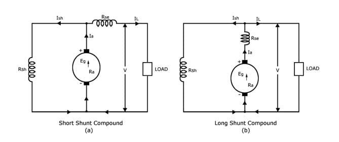
🔌 Short Shunt vs Long Shunt
Compound generators also come in two wiring styles:
- Short Shunt: The shunt winding connects only to the armature.
- Long Shunt: The shunt winding connects to both the armature and series winding together.
These are just different ways to connect the wires, depending on what the machine needs to do.
🔧 Tuning the Generator
We can even adjust the performance of a compound generator:
- Over-compounded: Voltage increases with load.
- Under-compounded: Voltage slightly drops with load.
- Flat-compounded: Voltage stays almost the same with load – perfect balance!
✅ Where Are They Used?
- Cumulatively compounded generators are preferred in real-life systems because they keep voltage steady, no matter how much load you connect.
- Separately excited generators are also good for when we need different voltage levels.
- But differentially compounded generators are best only for special uses like welding.
Short shunt:
In this, only shunt field winding is in parallel with the arm winding as shown in
Series field current, Ise=IL
Shunt field current, Ish = V+Ise Rse/Rsh
Terminal voltage V=Eg-IaRa-IseRse
Power developed in armature=EgIa
Power delivered to load=VIL
Long shunt:
In this, shunt field winding is in parallel with both series field and armature winding as shown
in
Series field current, Ise=Ia+IL+Ish
Shunt field current, Ish=V/Rsh
Terminal voltage, V=Eg-Ia(Ra+Rse)
Power developed in armature=Eg Ia
Power delivered to load=VIL
cumulatively compounded
In this type of DC generator, the field is produced by the shunt as well as series winding. The
shunt field is stronger than the series field. If the magnetic flux produced by the series winding assists
the flux produced by the shunt field winding, the generator is said to be Cumulatively
Compounded generator.
Differentially compounded
If the series field flux opposes the shunt field flux, the generator is said to be Differentially
Compounded.\
DC Generator Fails to Build Up EMF – and How to Fix It
A DC generator is a machine that changes mechanical energy into electrical energy. But sometimes, when we start the generator, it doesn’t give any voltage. Why? Let’s understand in a simple way.
1. No Residual Magnetism
Every generator needs a little leftover magnetism (called residual magnetism) in its poles to start working.
If this magnetism is missing, the generator won’t start producing voltage.
2. Field Wires Connected the Wrong Way
When there’s some residual magnetism, it creates a small voltage (called residual voltage). This small voltage helps build up more voltage.
But if the field wires are connected the wrong way, the magnetic force works in the opposite direction. Instead of helping, it destroys the leftover magnetism. As a result, the generator won’t build up voltage.
3. Field Resistance is Too High
- In a DC shunt generator, if the resistance of the field winding is too high, the voltage will not increase.
- In a DC series generator, if the load (the thing connected to the generator) has very high resistance, the voltage will also not build up.
4. Other Reasons
There are also a few more small issues that can stop the generator:
- If there is a break (open circuit) or a short circuit in the wires.
- If the brushes are loose or not touching properly.
- If the commutator is dirty or damaged.
How to Fix These Problems (Remedies)
Here are some simple ways to fix the problem:
✅ 1. Flash the Field
If there is no residual magnetism or the field wires are reversed, connect the field winding to an external DC supply for a few seconds.
This process is called “flashing the field”, and it helps bring back the magnetism.
✅ 2. Check the Field Resistance
- For a DC shunt generator, make sure the field resistance is less than the critical resistance.
- For a DC series generator, make sure the load resistance is not too high at the start.
✅ 3. Check All Connections and Parts
Clean the commutator if it’s dirty or has deep marks.
Make sure there are no broken or shorted wires.
Check that the brushes are tight and clean.
Losses and Efficiency
Whenever we use an electrical machine—like a motor or a generator—some energy gets wasted. This wasted energy is called a loss. It doesn’t help in doing useful work. Instead, it turns into heat and disappears into the air.
Let’s understand why these losses matter:
- Efficiency drops: The more energy is lost, the less efficient the machine becomes. That means we get less work from more electricity, which increases cost.
- Heat increases: These losses make the machine hot. If it becomes too hot, wires can melt, and insulation (the covering on wires) can get damaged.
- Performance goes down: The flow of extra current because of these losses causes voltage to drop, and the machine doesn’t work as well.
Types of Power Losses
Losses in a machine can happen in three main parts:
- Electrical Circuit Loss: This happens due to the resistance in wires. It is also called copper loss.
- Magnetic Circuit Loss: This occurs in the metal parts where the magnetic field flows. It includes hysteresis and eddy current loss.
- Mechanical Loss: This happens because of friction between moving parts or air resistance.
Some machines, especially high-voltage ones, may also have dielectric loss, which comes from the insulation getting slightly heated due to high electric stress.
Losses in a DC Machine (Like a DC Motor or Generator)
In a DC machine, losses are divided into two groups:
1. Variable Losses
These change depending on how much current is flowing.
- The main variable loss is copper loss, which happens in the armature winding (the part where electricity flows and spins the motor).
2. Constant Losses (Pc)
These losses stay nearly the same, no matter how much current flows.
- Core Loss: Happens in the iron part of the machine due to magnetic changes.
- Mechanical Loss: Due to friction in moving parts and air resistance.
- Shunt Field Copper Loss: Happens in the field winding, which creates the magnetic field.
- Stray Loss: Small unknown losses that can’t be easily measured but are always there.
What is Copper Loss?
Copper loss is a type of energy loss that happens inside electrical machines like motors and generators. You can also call it ohmic loss or resistive loss.
Now imagine this:
Electricity flows through wires, right? These wires are made of copper. But copper is not perfect — it has a little resistance. So, when current passes through the copper winding, some energy is lost in the form of heat. This is what we call copper loss.
🔥 Why Does Copper Loss Happen?
Copper loss happens because of resistance in the windings. It’s like trying to push water through a narrow pipe — it takes effort, and some of that effort is lost.
The loss is calculated using a simple formula:
Copper Loss = I² × R
Where:
- I is the current flowing through the winding
- R is the resistance of the winding
So, when the machine works harder (more load), the current increases, and so does the copper loss.
⚙️ Where Does Copper Loss Occur?
In a DC machine (like a DC motor or DC generator), copper loss happens in different places:
- Armature Winding
This is where the main current flows, so it has the biggest copper loss. - Compensating Winding
This winding also carries current, so it loses energy too. - Brushes and Brush Contacts
Even small metal contacts can have resistance, so there’s a tiny loss here. - Series Field Winding
Only in machines that use this winding — like series or compound machines. - Shunt Field Winding
This winding carries a small, steady current, so the copper loss here is almost constant, no matter how much load the machine carries.
📌 Important Point
- Copper loss increases when load increases. That’s why it’s also called a variable loss.
- But the copper loss in the shunt field winding doesn’t change much — so it’s often called a constant loss.
Core Loss –
Core loss is a type of loss that always remains the same, no matter how much load is connected to the machine. Whether the machine is running with no load or full load – core loss doesn’t change. That’s why it is also called no-load loss or open-circuit loss.
This loss happens in the iron core of the machine, which is why it’s also known as iron loss.
In a DC machine, the armature (the rotating part) has an iron core. When it rotates, it goes through magnetization again and again. This changing magnetism inside the iron core causes core loss.
Core loss has two main parts:
Hysteresis loss
Eddy current loss
Hysteresis Loss (हिस्टेरिसिस लॉस)
When we switch magnets on and off again and again, or keep changing their direction, something interesting happens inside the metal parts of a machine. The tiny magnets inside (called dipoles) start turning back and forth every time the magnetism changes. This repeated turning causes energy to be lost as heat. This type of energy loss is called hysteresis loss.
In DC machines, the rotating part of the motor, called the armature, passes through areas where the magnetic poles change — from North to South and then back again. Every time this happens, the magnetism in the core keeps changing. The same thing happens to the stator (the part that doesn’t move) because of something called armature reaction. All these changes cause heat loss inside the iron parts of the machine.
We can write hysteresis loss like this:
Hysteresis loss = η × fⁿ
Where:
- η is a number that depends on the type of material used and the size of the iron core.
- f is how many times the magnetism changes per second (frequency).
- n is a number between 1.5 and 2.5. Usually, we take it as 2. This is also called the Steinmetz constant.
When the machine is running with a load, the magnetism inside it changes even more. So, hysteresis loss becomes higher. This extra loss is counted as part of stray losses — the small losses that happen due to different small reasons in a machine.
To reduce hysteresis loss, we use materials that can become magnetic easily and don’t resist change. These are called high permeability materials. Using such materials helps keep the machine cool and more efficient.
Eddy Current Loss
When we use machines like electric motors or transformers, there is a part inside them called the magnetic core. This part helps in carrying magnetic energy. But sometimes, something unwanted happens inside this core—this is called eddy current loss.
Let’s understand this step by step, like a story:
🌪 What is Eddy Current Loss?
Imagine you are stirring water in a bowl with a spoon. As you move the spoon, small swirls or circles of water form around it. These are just like eddy currents—but instead of water, they happen in metal when magnetic energy keeps changing.
Whenever the magnetic field in the core changes again and again (which it does in motors and transformers), it creates small electric currents inside the metal. These currents are called eddy currents.
But there’s a problem!
These eddy currents create heat inside the core. This heat is a kind of energy that gets wasted. And that waste is what we call eddy current loss.
🔍 What Affects Eddy Current Loss?
The amount of this loss depends on:
- How strong the magnetic field is (called flux density),
- How fast it changes (called frequency),
- And how thick the metal sheets are (called laminations).
More strength, more speed, and more thickness mean more loss.
🛠 How Do We Reduce Eddy Current Loss?
Now, here’s the smart part. Engineers found a simple and clever way to reduce this loss.
Instead of using one big solid piece of metal, they use many thin sheets stacked together—like pages in a book. These sheets are called laminations.
Each sheet is:
- Very thin,
- Cut into the right shape,
- And covered with a special layer so electricity can’t flow easily between them.
This trick makes it hard for eddy currents to move around, and that reduces the heat and the loss.
Mechanical Loss
Mechanical loss happens because of moving parts inside a machine. When a machine runs, some parts like bearings and brushes rub against each other. This rubbing causes friction, which wastes a little power.
Also, when parts inside the machine spin, they cut through the air. This makes wind resistance, just like how you feel the wind push back when you run fast. This also wastes some energy.
Together, these two — friction and wind resistance — are called friction and windage loss. They are natural, but they reduce the machine’s total efficiency a bit.
🌟 Stray Loss
Stray loss is a little tricky. It happens when the machine is working under load — meaning, it’s doing its job and carrying electrical current.
Some of the magnetic force (called flux) that should stay inside the working parts of the machine, leaks out. This leaked flux touches other metal parts like the frame, shaft, brush holder, and bearings. This makes extra heat and wastes energy — this is a type of magnetic loss.
Also, the inside of the machine is not perfectly smooth. For example, there are slots to hold wires in the armature. Because of these, the magnetic force is not spread out evenly, which again causes a bit more loss.
This whole group of small, hard-to-catch losses is called stray load loss. Since it’s very difficult to measure exactly, engineers usually assume it to be about 1% of the total output power.
Efficiency (η)
Efficiency means how well something works. It tells us how much output we get from a machine when we give it some input.
If we give something energy, and it uses that energy without wasting much, then we say it is efficient.
In simple words,
Efficiency is the ability to give better results using less energy.
The more efficient a machine is, the less energy it wastes.
Efficiency of an Electric Generator
When we talk about an electric generator, it takes mechanical energy (like motion) and gives us electrical energy.
But some energy is always lost — like in heat, sound, or friction. So, we measure how much useful electrical energy we got from the total mechanical energy we gave.
The formula for efficiency is:
η=(Output Energy/Input Energy)×100
Or, for a generator:
η=(Electrical Output/Mechanical Input)×100

Applications of DC Generators
DC generators are used to produce direct current (DC) electricity. Based on how they’re made, they are divided into three main types: Shunt, Series, and Compound. Each type has its own special use. Let’s understand them one by one in a very simple way:
🔌 DC Shunt Generator
A DC Shunt Generator gives a voltage that stays almost the same all the time. That’s why it is perfect for things where a steady voltage is needed.
Where is it used?
- Lighting in homes and buildings – Because the voltage is stable, the lights don’t flicker.
- Electroplating – It helps in coating one metal over another smoothly.
- Exciters for Alternators – It helps start bigger machines that work with AC current.
- Battery charging – It gives a safe and steady current to charge batteries.
⚡ DC Series Generator
A DC Series Generator increases voltage as more current flows. It gives a rising voltage, which is helpful in some special uses.
Where is it used?
- Boosters – It boosts the voltage in long power lines to avoid power loss.
- Arc Lamps – These lamps need high voltage, so the series generator is a good fit.
🔧 DC Compound Generator
This type is a smart mix of both shunt and series generators. It is available in three forms: flat, over, and differential.
Where are they used?
- Flat Compound Generator – Used in places like offices, hostels, and lodges, where a steady and balanced power supply is needed.
- Over Compound Generator – Used when there is a long power line, and we want to make up for the voltage drop in the wires.
- Differential Compound Generator – These are used for DC welding machines, where controlled and stable power is needed for joining metal parts.
✅ In Short:
| Type of DC Generator | Main Use |
|---|---|
| DC Shunt | Lighting, plating, battery charging |
| DC Series | Voltage booster, arc lamps |
| DC Compound | Power supply to buildings, welding |
FAQ
I am an Electrical Engineer with qualifications in ITI, Diploma, and B.Tech. I have worked as an ITI college instructor for 3 years and have over 5 years of hands-on experience in the electrical field. The information shared on this website is based on trusted electrical engineering textbooks such as P.S. Bimbhra, B.L. Theraja, V.K. Mehta, and real-world practical experience.


